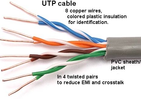
PVC jacket/sheath. Plastic insulation around each copper wire,
here exposed for illustration purposes only (never strip off the colored insulation):
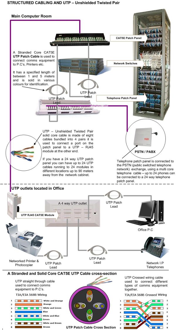
Cables: UTP and STP
UTP (unshielded twisted pair): 4 pairs (8 wires).
usually solid core for bulk/horizontal cable,
stranded (more flexible) for patch cords/cables/leads.
UTP categories: TIA/EIA-568-B. less attenuation, less crosstalk.
Cat 3 (obs.): 10Base-T. 3 twists/foot
Cat 5: OK for 100BASE-TX. 3 twists/inch on 24 gauge wire.
Cat 5e: better than Cat 5 for 1000BASE-T/full-duplex gigabit Ethernet.
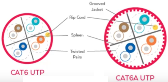
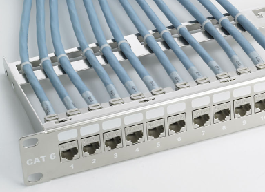
Cat 6 (2002): better for crosstalk and noise. 10Gbps@55m. 22-24
gauge. sometimes internal separators to reduce crosstalk
Cat 6a: 2008. UTP for 10Gbps@100m. Can be flat.
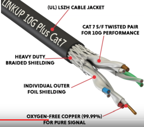
Cat 7: pairs shielded and cable shielded. 10GbE
Cat 8: pairs shielded and cable shielded. 40GbE@30m
Connectors, wall plates / face plates, patch panel must be same category. Certify.
Max propagation delay: 548 nsec/100m. Different pairs have different twist rates, thus
different lengths, thus different propagation delays.
Do not cut, bend, stretch, crush, pinch.
Thin cable uses 28 gauge, 32 gauge.
Rating: CMR: indoors; CMP: plenum; CMX: outdoors
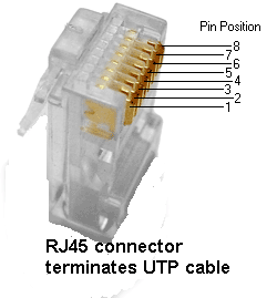
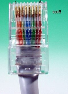
RJ-45 (8P8C) connector/plug into port/jack. Terminates the cable.
All 8 insulated wires visible at very end of it; jacket inside
it. <=1" of jacket stripped, <=1/2" untwisted (Cat6:<3/8" untwisted).
gold-plated pins. Cable wire contacting pin for metal-to-metal electron flow.
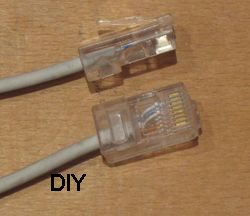
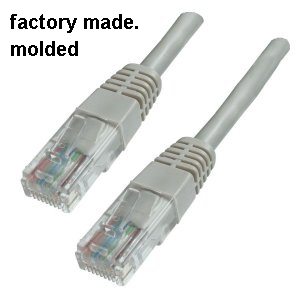
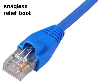
Factory-made cables with molded connectors. snagless.
Snap tab to lock into jack.
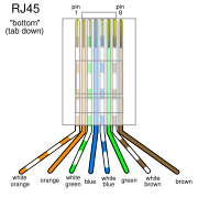
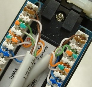
What color wire to what pin of RJ-45. Wire-to-pin assignment (pinout) as per 568A/B spec.:
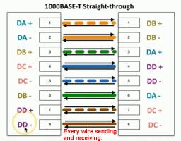
straight-through cable: same wires at each end.
For connecting NIC to hub/switch.
cross-over cable: wires 1 and 2 (oranges), and 3 and 6 (greens)
switched at each end (1-3, 2-6). Essentially a 568B at one end, 568A at other end.
For connecting two NICs or two hubs/switches.
GbE: blue and brown pairs also crossover. No longer can say is 586A at one end,
568B at the other.
Auto-MDIX (Auto Sense) (in all gigabit and newer 10/100Mbps) renders distinction obsolete.
10/100Mbps: host NIC: wires 1 and 2 Tx, 3 and 6 Rx (4578 unused);
switch: 1,2 Rx and 3,6 Tx
1/10Gbps: all 4 pairs used and each pair used to both Tx and Rx.
Make your own patch cable with cable jacket cutter & stripper (or scissors);
untwist, straighten, flatten and align wires in chosen order (568A or 568B);
blade to cut aligned wires;
insert into RJ45 module;
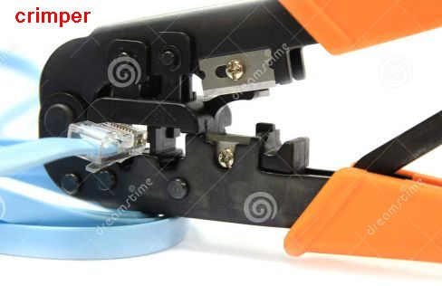
crimper for squeezing the connector
so that cable wires contacting the pins.
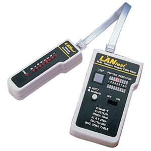
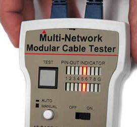
Cable tester: continuity: no shorts on each wire; what wire to what wire on other end;
Better quality/expense tester: certify: cable at max capability of spec?
amounts of crosstalk, attenuation, resistance, interference.
Water corrosion at wall plate, broken wires at patch panel.
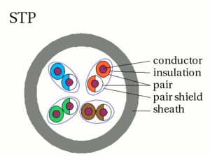
STP: each pair shielded for EMI protection. for electrically noisy environments
eg. factories. Proper grounding of shield at wall plate is important.
aluminum, or better, braided copper, foil.
Screened UTP or STP: outer metal screen for more EMI protection.
S/FTP braided shielding around entire, foil around each pair.
F/UTP foil around entire, no shielding around pairs.
Ethernet AutoNegotiation to set speed and duplex. (Not in frames.)
If it is off on the NIC, switch senses speed and if 10 or 100 sets duplex to half which
might be mismatch, else to full.
Pulse every 16ms (1/60s) when not transceiving.
Also, sometimes?/periodically?/at connection? send 1 or 2 bytes of info about speed and
duplex capability.
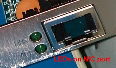
NIC LEDs (light-emitting diodes) for LiNK/CONNectivity (something live on the other end)
and ACTivity (frame input or output).
(sometimes has colors for 100/1G/10G speed indicator)
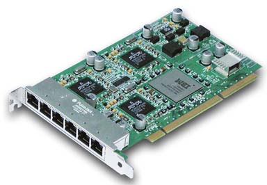
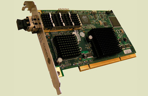
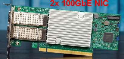
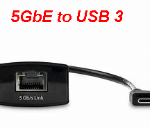
Expansion cards:
Gigabit 6 port NIC
10GbE NIC
100GbE NIC
5GbE NIC to USB 3
Each wall plate / patch bay jack is labelled with some identifier,
matched with same on patch panel jack. If unknown, use toner&probe to locate.
Wall plate has no electronics.
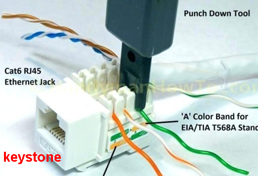
Inside of a wall plate: bulk cable directly connected (punched down). Front has RJ-45 jack.
E.g. inside wall plate and at other end of bulk/horizontal cable in telecom closet's patch panel.

Cable installation:
external installation: in room(s) to hub/switch or to wiring closet. Molded
floor protectors, raceways and conduits, staples and clips, cable ties or velcro.
drilling between rooms and floors problematic.
internal installation (professional): cables are run inside walls, floors, ceilings.
Wall/face plates installed. Cables connected to patch panel in wiring closet.
patch cable from computer to wall plate jack.
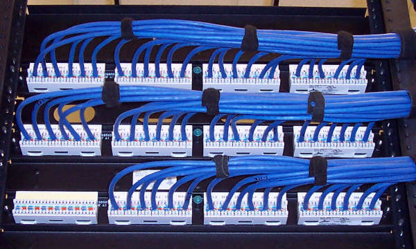
Bulk cable ("horizontal cabling") pulled from there to wiring/"telecom closet/room's"
110 patch panel. Also: Krone, BIX block.
[66 punchdown block is for analog telephone cables.].
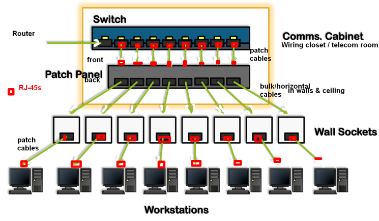
Patch panel has no electronics. Modular patch panel uses keystones.
A patch cable from patch panel to switch.
NIC--patch cable--wall plate--bulk cable--patch panel--patch cable--switch port
horizontal cable <= 90m. patch cables total <=10m.
Also, maybe, "backbone cabling" to "equipment room"/MDF (main distribution frame)
eg. servers, and to "entrance facility" where network enters the building.
Pulling cable tools: cable puller, telepole, fish tape, ball of string.
Fast&Gigabit Ethernets: only two switches daisy-chainable? but stackable switches many?
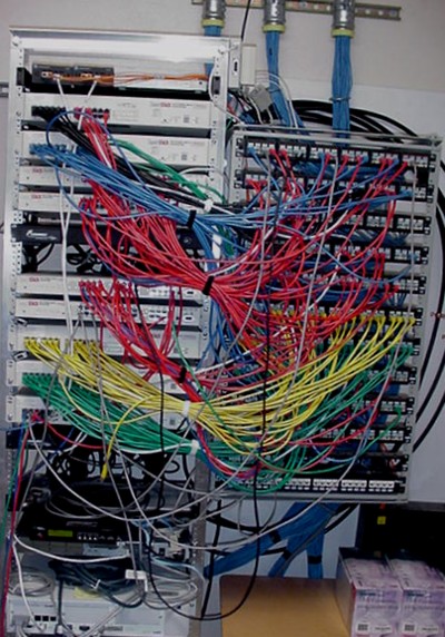
Wiring closet (IDF intermediate distribution frame): On left, switches in equipment rack.
On top right, bundle of bulk cables from rooms' wall plates of this floor of building.
On right, each cable is punched down on back side of patch panel, on the front side of which
are RJ-45 jacks.

Lack of connectivity between PC and hub/switch:
HW: bad cable (3) or termination (6), bad NIC/port (corroded, unseated, fried),
device powered off, plug not fully in jack (broken tab).
SW: bad/unistalled driver, port disabled, speed or duplex mismatch (can cause Late Collisions),
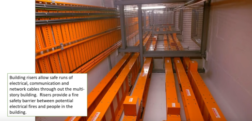
Structured cabling
Building backbone
plenum-rated cable/sheath: slow-burning, fire-resistant/flame-retardant
casing that emits little smoke for cable in the plenum (space between
drop ceiling and floor, return airflow not in ducts). teflon? Not riser cable.